
Table of Contents
Playpens Regulations
C.R.C., c. 932
CANADA CONSUMER PRODUCT SAFETY ACT
HAZARDOUS PRODUCTS ACT
Regulations Respecting the Sale, Advertising and Importation of Playpens (Play Yards) for Children
Short Title
1 These Regulations may be cited as the Playpens Regulations.
Interpretation
2 In these Regulations,
- Act
Act means the Hazardous Products Act; (Loi)
- mesh
mesh means any netting used to form the sides, top or bottom of a product; (maille)
- product
product means a playpen (play yard) for children that is included in item 26 of Part II of Schedule I to the Act. (produit)
- SOR/91-266, s. 2
General
3 (1) A product may be advertised, sold or imported into Canada only if it meets the applicable requirements of these Regulations.
(2) Any information or statement required by these Regulations to accompany a product or to be printed on or permanently affixed to a product or its container shall be in both official languages.
- SOR/91-266, s. 3(F)
Labelling and Instructions for Assembly
4 (1) Every product shall have indelibly printed on it, or otherwise permanently affixed to it, the following information, clearly and prominently displayed in letters and numerals not less than 2.4 mm (0.09 inch) in height:
(a) the name and principal place of business of the person by or for whom the product is made;
(b) the model name or model number of the product; and
(c) the month and year of manufacture of the product.
(2) Every product shall have indelibly printed on it, or otherwise permanently affixed to it, immediately following the information referred to in subsection (1), the following statement, clearly and prominently displayed in letters not less than 2.4 mm (0.09 inch) in height:
“This product complies with the requirements of the Playpens Regulations (Canada)”
(3) Every container in which a product is sold or is to be sold shall have indelibly printed on it, or otherwise permanently affixed to it, the information and statement required by subsections (1) and (2) clearly and prominently displayed in letters not less than 2.4 mm (0.09 inch) in height.
(4) Every product shall, unless sold fully assembled, bear or be accompanied by instructions that clearly state and show how the product is to be assembled.
Design, Construction and Performance of Product
5 (1) The size of the openings in any mesh shall be such that, when the product is tested in accordance with the procedures specified in Schedule I, the tip of the probe described in Schedule II shall not be capable of passing through an opening.
(2) No mesh shall, when tested in accordance with the procedures specified in Schedule III,
(a) break or rupture; or
(b) become separated from its supporting structure or attachments.
(3) Every exposed wooden or plastic part of a product shall be
(a) smoothly finished to eliminate rough or sharp edges, corners or surfaces; and
(b) free from splits, cracks or other defects.
(4) Every metal part of a product shall be free from burrs, sharp edges, corners or points and any cut end of metal tubing that is accessible to the occupant shall be protected by a cap that will remain in place when subjected to a load of 90N (20.23 lb.) applied in any direction.
(5) The threaded end of every bolt of a product shall be protected by an acorn nut or other suitable device or so placed that contact by the occupant with the threaded end cannot occur.
(6) Every component of a product made of a textile material or plastic film shall, when tested in accordance with the method prescribed in the Standard Method of Test for Flammability of Clothing Textiles ASTM D 1230-61, being a standard of the American Society for Testing and Materials, have a time of flame spread of not less than seven seconds.
(7) Any open hole drilled in a metal, plastic, wood component or component of similar material of a product that is exposed to the occupant shall be less than 3.0 mm (0.12 inch) or more than 10.0 mm (0.39 inch) in diameter.
(8) No product shall be equipped with more than two wheels or casters or provisions for their attachment.
(9) Every component that is accessible to the occupant and is small enough to be placed in the small parts cylinder described in Schedule IV shall be so fitted or affixed to the product that upon the application in any direction of a force of 90N (20.23 lb.) to the component, the component does not become detached from the product.
(10) No cord, tape or similar material having a free, stretched length in excess of 180 mm (7.10 inches) shall be attached to a product.
(11) Any product that folds shall contain a locking device or other design feature that will prevent the product from folding or collapsing spontaneously when tested in accordance with Schedule V.
(12) Any portion of the floor of a product shall be capable of supporting a load of 220N (49.4 lb.) uniformly distributed over an area of 4.5 × 104 mm2 (69.75 sq. inches) for a period of one minute without visually perceptible damage to the product or any component thereof.
(13) Every product shall be so designed and constructed as to preclude injury to the occupant from any scissoring, shearing or pinching.
(14) The vertical distance between the top of the floor and the top of the upper framing member of the product shall not be less than 480 mm (18.89 inches).
(15) All stitching used in a product shall be lock-stitching.
Footnote *(16) All materials used in the construction of a product and any of its components shall comply with the requirements of paragraphs 10(a) to (c) of the Hazardous Products (Toys) Regulations.
Return to footnote *Your attention is directed to item 9 of Part I of the Schedule to the Act (decorative or protective coatings).
(17) When subjected to the test described in Schedule V, all support points of a product shall remain in contact with the inclined plane.
- SOR/2004-65, s. 8
SCHEDULE I(Section 5)Procedure for the Determination of Mesh Opening Sizes
1 Cut a sample of mesh 1 foot square from the mesh of the product.
2 Apply a uniformly distributed load of 0.15 N/mm (10 lb. per running foot) to two opposite edges of the sample so as to induce a state of uniaxial tension in the sample.
3 With the sample loaded in accordance with section 2, attempt to insert the tip of the probe described in Schedule II through openings in the mesh without cutting the fibres of the material using a force not exceeding 22N (4.95 lb.) at 10 randomly located areas in the sample.
4 Remove the uniformly distributed load and reapply to the other two opposite edges of the sample so as to induce a state of uniaxial tension in the sample normal to that produced pursuant to section 2.
5 Repeat the procedure described in section 3.
SCHEDULE II(Section 5 and Schedule I)A Probe Designed To Evaluate Mesh Opening Sizes
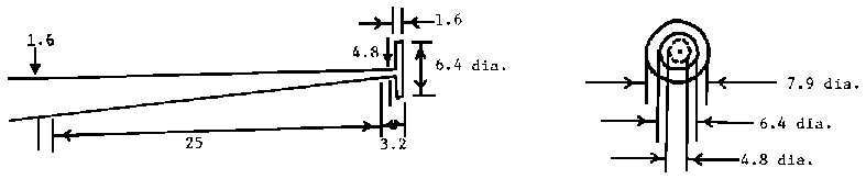
Equivalent Imperial Measurements
1.6 mm = .063 inch
3.2 mm = .126 inch
4.8 mm = .189 inch
6.4 mm = .252 inch
7.9 mm = .311 inch
25 mm = .984 inch
Note: All measurements shown in the above diagrams are in millimetres.
SCHEDULE III(Section 5)Test for Strength of Mesh and Integrity of Attachment
1 (1) Place the product, assembled in accordance with the manufacturer’s instructions, on its side so that its side lies in a horizontal plane.
(2) Any blocking or support necessary to maintain the position described in subsection (1) may be used if the blocking does not act directly on the frame of the side under test.
2 (1) Apply a load of 90N (20.23 lb.) acting uniformly over rectangular areas 150 mm x 75 mm (5.9” x 2.9”) and with the 150 mm (5.9”) sides running transversely to the side, in the following manner
(a) gradually apply load over 1 second;
(b) allow full load to act for 10 seconds;
(c) gradually remove load over 1 second; and
(d) allow 10-second recovery time.
(2) Repeat 10 times the loading procedure described in subsection (1).
3 The loading procedure described in subsection 2(1) shall be applied to three areas of each side of the product as follows:
(a) at the geometrical centre of the side or, where exterior framing inteferes with the test, as close as possible to the geometric centre;
(b) at the top rail of the side, with the closer 75 mm (2.9”) edge of the load block between 25 mm and 50 mm (1” and 2”) from the centre of the rail at the transverse centre line of the panel; and
(c) at the bottom rail with the closer 75 mm (2.9”) edge of the load block between 25 mm and 50 mm (1” and 2”) from the centre of the rail at the transverse centre line of the panel.
SCHEDULE IV(Subsection 5(9))Small Parts Cylinder
1 A small parts cylinder of the design and dimensions shown in the following diagram shall be used for the purpose of measuring components described in subsection 5(9):
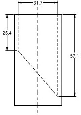
Notes:
– Not to scale
– All dimensions in mm
- SOR/2004-65, s. 9
SCHEDULE V(Section 5)Test for Stability of the Product
1 Assemble the product in accordance with the manufacturer’s instructions.
2 Place the product on a sheet of 19 mm (3/4”) plywood of such a size that all support points or legs are at least 50 mm (1.97”) from any edge of the plywood.
3 Orient the product so that one set of support points or legs in the same plane is parallel to the edge of the plywood.
4 Place the 23 kg (51.6 lb.) test device described in Schedule VI on the floor of the product with the 300 mm (11.8”) edge parallel to the side of the product and as close as possible to the side of the product that is parallel to the edge of the plywood.
5 Tilt the plywood about the parallel edge until the plywood forms an angle of 10° with the horizontal.
6 Repeat the procedures set out in sections 2 to 5 so that the stability of the product is evaluated about each set of support points or legs in the same vertical plane.
NOTE: Downslope edges of the support points may be blocked to prevent slippage during the test.
SCHEDULE VI(Schedule V)23 kg (51.6 lb) Stability Test Device
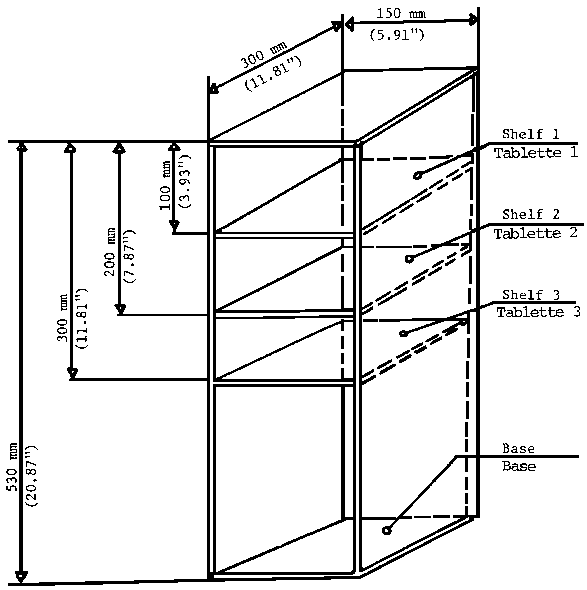
Ballast Loads:
Shelves: 1 to 3-6.75 kg (14.91 lb.) each.
Base: As required to make up total weight of 23 kg (51.6 lb.).
Page Details
- Date modified: